Shackle Size Selection: Reading WLL Markings and Matching Pin Diameter
Select a shackle by its marked Working Load Limit, never by its physical size, and check that the pin diameter and jaw width actually fit the sling eye, masterlink, or lifting point they connect. The WLL, size, grade, and traceability marks forged into the body tell you everything — if you know how to read them.
Why "size" and "capacity" are two different questions
The single most common shackle mistake we see is choosing by eye: a shackle that looks big enough. Shackle capacity depends on material grade as much as on dimensions — two shackles of identical body diameter can carry very different loads if one is a general-engineering shackle and the other a high-tensile alloy shackle to EN 13889 or US Federal Specification RR-C-271, the specification behind the familiar Crosby catalogue ratings. IS/ISO 2415:2004 itself recognises three grades — 4, 6 and 8 — for working load limits from 0.32 t to 100 t, and the same body diameter carries a different WLL in each. That is why the rated WLL is forged onto the body, and why the marking — not the appearance — is the selection basis.
The second question is fit. A shackle whose WLL is adequate can still be the wrong shackle if the pin is too large for the lifting point hole, the jaw too narrow for the sling eye, or the bow too small for the number of legs bearing on it. Selection is capacity first, geometry second — and both must pass.
Reading the markings on a rated shackle
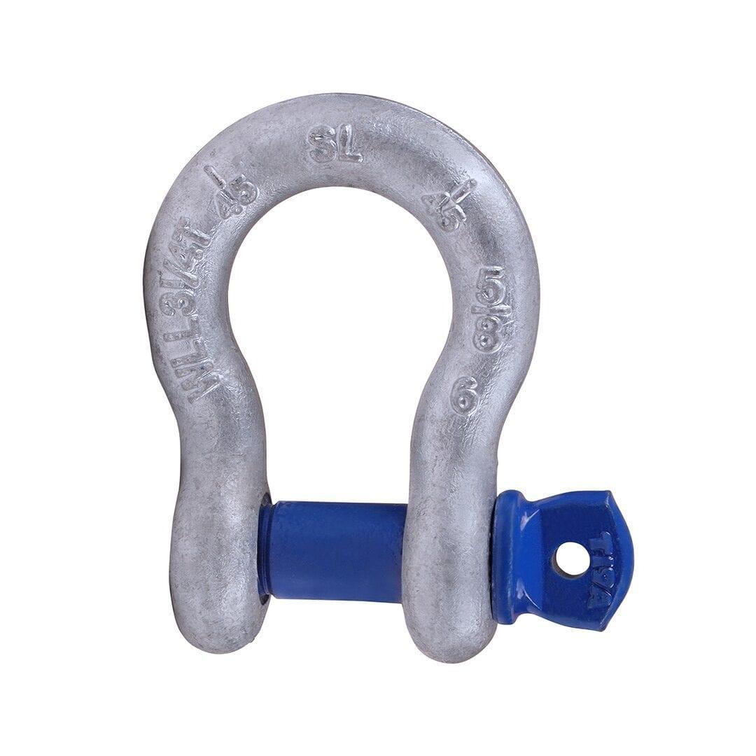
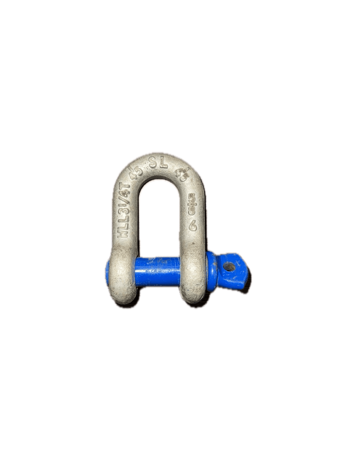
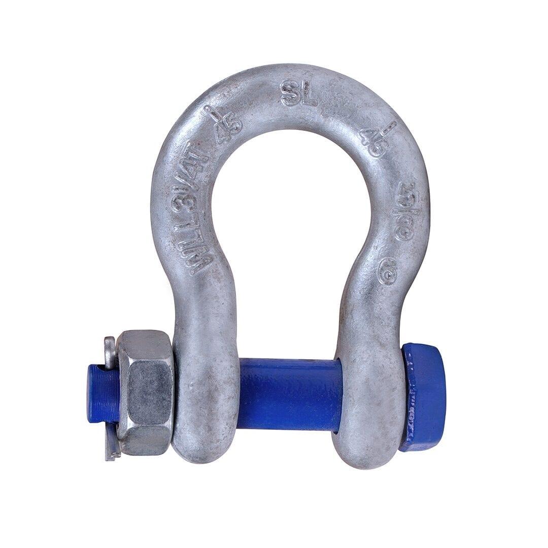
A compliant lifting shackle carries permanent, legible markings, typically forged or stamped on the body and pin:
- WLL — the Working Load Limit, in tonnes (e.g. "WLL 4.75t"). This is the maximum load for in-line loading of a new shackle; see WLL vs SWL explained for how it relates to proof load and breaking load.
- Nominal size — commonly the body (bow) material diameter. On shackles to IS/ISO 2415 the pin is always thicker than the body: the standard derives both dimensions from the WLL and the grade, and sets the pin diameter above the body diameter by design. So never use "size" alone to check hole fit — read the pin diameter in the maker's table.
- Manufacturer's mark — the maker's name or symbol, which ties the shackle to its test certificate.
- Grade or specification reference — such as the grade marking under IS/ISO 2415 or EN 13889, or the manufacturer's series designation.
- Traceability code — a batch or serial code linking the shackle to its manufacturing records and certificate.
- CE or other conformity marking where applicable to the market of supply.
If any of these are missing or unreadable, the shackle cannot be verified against a certificate and should be withdrawn from lifting service.
Matching pin diameter and jaw to the connection
Getting the geometry right protects both the shackle and whatever it connects to:
| Check | What to verify | What goes wrong otherwise |
|---|---|---|
| Pin vs lifting point hole | Pin diameter close to the hole size, without forcing | A loose pin point-loads the hole edge; an oversized pin will not seat |
| Jaw width vs sling eye or plate | The connected item sits centrally without jamming or excessive slack | Off-centre loading bends the pin and side-loads the body |
| Bow room for multi-leg slings | Sling legs bear on the bow, not on the pin threads, symmetrically placed | Crosby: two legs loaded symmetrically in the bow may be used to the full WLL up to a 120° included angle — never exceed 120°. Beyond that, or with unequal legs, the shackle is outside its rating |
| Pin engagement | Screw pin fully seated, shoulder flush; safety bolt with nut and split pin fitted | Partially engaged threads carry the load on a few threads |
| Loading direction | Load in line with the shackle centreline, in the plane of the bow | Side loading reduces the usable WLL — see Crosby's side-load reduction below; round-pin shackles must never be side loaded |
Two different "angles": included angle and side load
Riggers often treat these as one, and they behave differently. The included angle is the angle between two sling legs that both bear in the bow. Crosby's published rule for its shackles is a hard ceiling, not a taper: symmetrically loaded legs may be used at the full WLL up to 120° included angle, and never beyond it. There is no reduction chart to read below 120°.
Side loading is a load pulling out of the plane of the bow — the shackle loaded sideways. That is the case with a reduction table. For Crosby screw-pin and bolt-type shackles up to 120 t, the published percentage reductions from the rated WLL are:
| Angle from in-line | Reduce the WLL by |
|---|---|
| 0° – 10° | 0 % |
| 11° – 20° | 15 % |
| 21° – 30° | 25 % |
| 31° – 45° | 30 % |
| 46° – 55° | 40 % |
| 56° – 70° | 45 % |
| 71° – 90° | 50 % |
These are Crosby's figures for Crosby product, not a universal rigging rule — other makers publish their own tables, and Crosby's own table changes above that size. Read the figures as reductions: at 90° the shackle keeps half its WLL, it does not gain a 50 % rating. Round-pin shackles (Crosby G/S-213 and G/S-215) are excluded entirely — never side-load them, and never use them to gather multiple sling legs.
Bow or dee, screw pin or safety bolt
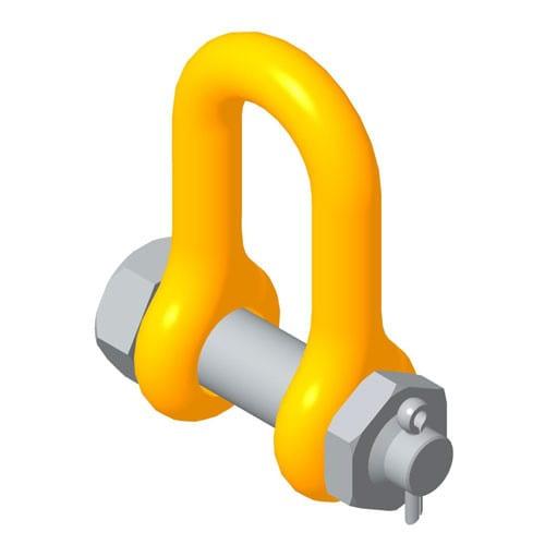
Body pattern and pin type are the two remaining choices. A dee (chain) shackle is intended for single in-line pulls; a bow (anchor) shackle accepts multiple legs or changing load directions. Our guide to bow shackles vs D-shackles covers this choice in detail. On pins: a screw pin shackle is quick to use and suits temporary connections that are made and broken frequently, but the pin can unscrew if the shackle is subjected to vibration or if the pin can roll under load — for long-term installations, mousing the pin or specifying a safety-bolt (nut and split pin) pattern is the sound choice. A round pin held only by a cotter suits in-line, tie-down style connections and nothing that can pull sideways.
Proof load, breaking load and design factor — name the specification
Proof load and minimum breaking load are separate, higher figures stated on the certificate, and the ratio between them and the WLL depends on which specification the shackle is built to. Under IS/ISO 2415:2004 every shackle is proof-tested to 2.0 × WLL and has a minimum ultimate strength of 4 × WLL — a design factor of 4:1. Shackles built to ASME B30.26 / RR-C-271 practice work to a minimum 5:1, and Crosby publishes 6:1 for most of its shackle sizes. A shackle sold in India can legitimately be any of the three, so the certificate — not a rule of thumb — tells you which applies. Whatever the factor, it is not spare capacity: you never "use up" that margin deliberately.
Indian standards, certification, and the test-house view
In India, dee and bow shackles for general lifting purposes are covered by IS/ISO 2415:2004 (superseding IS 6132:2003), while imported rated shackles typically conform to EN 13889 (forged steel shackles, grade 6) or to US Fed. Spec. RR-C-271, with rigging hardware practice under ASME B30.26.
The statutory regime depends on where the shackle works. At ports, a shackle is "loose gear" under regulation 2(o) of the Dock Workers (Safety, Health and Welfare) Regulations, 1990: it is tested by a competent person before first use, retested at least every five years and thoroughly examined at least once every twelve months, with entries in the statutory register; for dock work the competent person is recognised by DGFASLI as Chief Inspector of Dock Safety. In a factory, section 29(1)(a)(iii) of the Factories Act 1948 requires every chain, rope and lifting tackle to be thoroughly examined by a competent person at least once in every period of twelve months; there the competent person is recognised by the state Chief Inspector of Factories, and the state's Factories Rules set the register and the certificate forms.
One dock-work point customers often misread: regulation 49 of the Dock Workers Regulations requires certain loose gear to be annealed periodically, but the same regulation forbids heat treatment of loose gear made from high-tensile or alloy steel. Alloy shackles — Crosby, EN 13889 Grade 6, IS/ISO 2415 Grades 6 and 8 — fall in that exempt category and must not be sent for annealing.
Sealinkers has been testing and certifying rigging hardware at Darukhana, Mumbai since 1977. With our in-house test house and its 1,200 T proof-load test bed, we proof-test shackles and issue the test and examination certificates — and we supply Crosby shackles with full traceability. A pattern we see repeatedly on examination: shackles bought correctly but with pins swapped between bodies over years of use. A pin from another shackle — even the same nominal size — voids the certified assembly.
Selection checklist
- Establish the load per connection point, including any angle effects from multi-leg slings
- Select on marked WLL with the required margin — never on physical size or appearance
- Confirm the specification: IS/ISO 2415:2004, EN 13889, or RR-C-271 per your compliance requirement
- Check pin diameter against the lifting point hole, and jaw width against the sling eye or plate
- Choose bow pattern for multi-leg or changing-direction loads; dee for in-line pulls
- Keep two-leg included angles in the bow at or below 120°, and apply the maker's side-load reduction for any out-of-plane pull
- Choose safety-bolt pins for permanent or vibrating installations; mouse screw pins that stay rigged
- Verify markings are legible: WLL, size, maker, grade, traceability code
- Match the shackle to its test certificate before first use, and keep it in the examination register
Never replace a shackle pin with a bolt, a pin from a different shackle, or any unrated substitute. A commercial bolt has neither the material grade nor the fit of the original pin, and the assembly's WLL no longer exists. Likewise, never side-load a dee shackle or a round-pin shackle, or load a screw pin in a way that allows it to roll and unscrew — all are recurring causes of dropped loads.
Frequently asked questions
What does the WLL marking on a shackle actually mean?
It is the maximum load the shackle is rated to carry when new, loaded in line through the bow and pin. It already includes the design factor against breaking load — 4:1 under IS/ISO 2415, 5:1 under ASME B30.26 practice, 6:1 on most Crosby shackles — and you never "use up" that margin deliberately. Proof load and minimum breaking load are separate, higher figures stated on the certificate.
Does shackle size refer to the pin or the body?
Nominal size refers to the body (bow) material diameter, and on any shackle to IS/ISO 2415 the pin is larger — the standard derives both dimensions from the WLL and grade. Always check both dimensions in the manufacturer's tables when hole fit matters — never assume from the nominal size.
Can I use a shackle at an angle?
Two different things get called "angle". Legs bearing symmetrically in the bow of a Crosby shackle may be used at the full WLL up to a 120° included angle — never beyond it. A side load, pulling out of the plane of the bow, does reduce capacity: Crosby's table runs from no reduction within 10° of in-line to a 50 % reduction at 90°. Round-pin shackles must never be side loaded. Remember the sling legs themselves also lose capacity with angle, as explained in sling angle effects on SWL.
How do I know if an old shackle is still safe?
Check the markings are legible, the pin is the original and seats fully, and the body and pin show no cracks, distortion or heavy corrosion. Wear is measured, not judged: for dock work, regulation 46 of the Dock Workers (Safety, Health and Welfare) Regulations, 1990 sets numeric limits — loose gear that has stretched by more than 5 % or lost more than 10 % of an original dimension is withdrawn — and elsewhere the maker's discard criteria apply. Then confirm it is within its periodic examination and appears in the register. If any check fails, quarantine it.
Are galvanised shackles weaker than painted ones?
No — the finish protects against corrosion and does not set the rating. The grade of steel and the manufacturer's certification determine the WLL. What matters is that the markings remain legible through the finish.
Do shackles need proof-load testing in India?
Yes, and the trigger depends on where the shackle works. Every rated shackle is proof-tested by the manufacturer before supply — to 2.0 × WLL under IS/ISO 2415. In dock work, loose gear is tested by a competent person before first use and retested at least every five years, with a thorough examination at least every twelve months. In a factory, the Factories Act requires a thorough examination at least every twelve months, and the state's Factories Rules set when a test is required and which forms record it. Retesting after repair, or when a certificate is missing, is core work for our test bed at Sealinkers.
Browse our shackle range and certified slings, or talk to us about matching Crosby, IS/ISO 2415, and EN 13889 hardware to your lifting plan with certificates included.
Related Guides
Ready to put this into practice?
Every item ships certified, and our in-house test house backs it with the paperwork.
Sealinkers Engineering
Rigging & Lifting Engineering Team
Sealinkers has supplied and certified rigging, lifting and mooring equipment from Darukhana, Mumbai since 1977. These guides are written and checked by the engineers who specify this gear and proof-load it on our own test bed.
- in-house test house — proof-load bed from 1 to 1,200 tonnes
- Proof-load testing and certification in-house since 1977, Darukhana, Mumbai
- Class-society interfaces: IRS, ABS, LRS and BV